Pipes
Serves to specify pipes, on the one hand by definition of the node connections of the pipe in the network, on the other hand by the allocation of the pipe geometric data (pipe class, length, pressure loss coefficient). Similarly to the node input, it is possible to input the networks positions flow, and return to the KLB leader at the same time.
Pipe dialog for a 2-leader long-distance heating network with indicated list of inflexion points and opened combination list of the pipe classes in return.

Pipe - Give the pipe a name here. The name of the pipe is freely selectable and is independent of the linkage with nodes.
✍ During graphic input (see Create Pipe) sisHYD assigns a pipe name automatically which results from the name connected to the initial and end nodes by "-". If this name is already assigned (a parallel pipe was laid), sisHYD generates a unique name.
Arbitrary renaming of the pipe to another unique name is permissible. sisHYD checks whether the name is already used by another network element and issues a warning if necessary.
General Tab
Start and End Nodes - The combination lists permit the selection of an initial and end node for the pipe.
⚠ A change of the selection changes the network topology! Changing a start and/or end Node has no effect on the assigned pipe names and the length.
Zone - Assigns the pipe to one of the configured zones.
✍ The allocation of zones is optional. It is very helpful to differentiate the pipes according to zones, in particular to calculate dimensions and costs. Calculation can be limited selectively to certain zones. See Zone.
Symmetrical supply and return - This marker field controls the behavior of the pipe data on the network positions supply, return during input. If the field is activated, all changes to entries in the supply and in the return are applied and reversed.
Supply/Return/KLB leader - The marker fields specify whether the pipe at the network position concerned is present or not. If a field is not marked, the input fields of the network position are blocked.
⚠ Changes to the marker fields modify the network topology!
Pipe class - The combination field indicates the currently selected pipe class of the pipe (at the appropriate network position) and enables the conversion to one of the available Pipe classes.
Pipe length - You enter the pipe length at the corresponding network position into the input field.
✍ The pipe lengths at the different network positions do not have to be identical. With graphic input of pipes, the pipe length is calculated automatically.
✍ For the additional examination and if necessary correction of the pipe lengths, there is an assistant available – see Update pipe lengths.
Zeta value - The numerical value entered here is the sum of the pressure loss coefficients, independent of length, of fittings and detours in the pipe. The value of the number in this field can be entered manually or automatically when fittings are inputted using the Fittings tab.
⚠ As soon as entries are present in the list of the special fittings, this field is blocked for manual input. An overwriting of the values would lead to contradictory information.
✍ The pressure loss coefficients represent one of the possibilities to create additional resistances by special fittings and detours. The application of a global factor for the dynamic pressure losses can be seen as an alternative possibility. See Steady State Network Calculation.
Isolated - The marker field enables the isolation of the pipe for network calculation.
✍ The switch has the advantage that no valve must be built into the network, in order to interrupt the network for a calculation here. The Zeta value of the piping and thus the hydraulic calculation of the pipe are not changed by marking this field. Enter the Zeta value corresponding to the existing slidegate valve into the list of the Zeta values (or directly into the Zeta value field) yourself, if necessary. See "Fittings" Tab" below.
⚠ When this switch is pressed, the pipe is not yet closed. The state "on" or "off" is set in the calculation specifications Isolation Valves Tab for each individual network calculation.
Price category – Assigns a price category within the range of 1 to 6 to the pipe for the determination of the moving costs. The moving costs are calculated from the product of the price category indicated by pipe length and pipe class moving costs.
 Individual exterior temperature - As standard,
sisHYD calculates the heat losses of a pipe with the temperature default of
network calculation. If the field for the individual exterior temperature is
marked, the thermal calculation of the pipe with the exterior temperature
registered here takes place.
Individual exterior temperature - As standard,
sisHYD calculates the heat losses of a pipe with the temperature default of
network calculation. If the field for the individual exterior temperature is
marked, the thermal calculation of the pipe with the exterior temperature
registered here takes place.
✍ In the reports the exterior temperature for the pipe is listed only if it was individually given. Otherwise a "*" appears in the report lists to show that the global value for the outside temperature was taken.
Inflexion Points Tab

Shows a list that can be edited, with the pipe inflexion points between initial and end nodes (an empty list, if no inflexion points are present). The inflexion points are sorted in such a way that they indicate the process from initial to end node.
✍ Using the "right button" menu, the sequence of the inflexion points can be manipulated and new inflexion points can be inserted or existing inflexion points deleted.
⚠ Manipulations at the inflexion point list cause a changed diagram of the pipe process. The pipe length is not changed.
For the change of the pipe process diagram tools are available, which can also recalculate the pipe length. Alternatively, the assistant Update pipe lengths is available for the examination and correction of pipe lengths.
Fittings Tab
Using the tab Fittings additional resistances are allocated to the pipe and the total of the coefficients of drag is calculated.
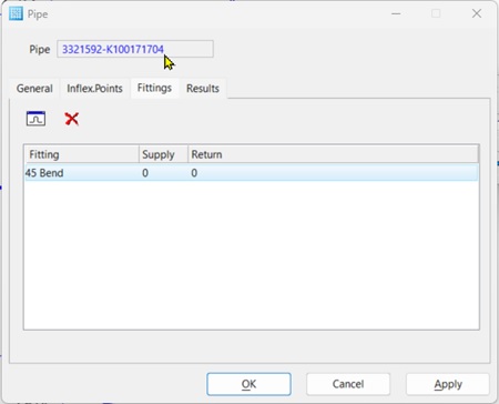
✍ As soon as Zeta values are entered into this list, it is no longer possible to change the Zeta value manually. sisHYD then computes the Zeta value using the special fittings registered here. In order to register Zeta values again manually, this list must contain no rows here.
 Open dialog "Coefficients of drag"
The dialog mask "coefficients of drag" is opened by clicking on the symbol.

Deletes the selected entry from the list of the special fittings.
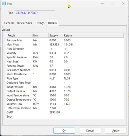
Result Tab
Using the tab, you see directly the calculation results for the pipe. The height of the dialog mask is adaptable to be able to show the results list completely.
Calculation
Indicates the names of the network calculation to which the results belong.
List of the results
The following results for the pipe are computed and indicated subject to the module :
- Pressure Loss – The sum of all pressure losses in the pipe.
- Mass Flow – Is the computed pipe flow.
- Velocity – Flow rate.
- Specific Pressure Loss – Specific pressure loss = dynamic pressure loss related to the pipe length.
- Exit dampness – Dampness in the piping exit (only for steam networks).
- Dyn. pressure loss – Is the pressure loss due to friction in pipes.
- Heat Loss – Is the entire energy dissipation delivered over the piping surface.
- Transportation – sisHYD estimates the transported thermal output of the flow leader (and KLB leader) according to the following formula for long-distance heating systems:
- Resistance number
- Zeta value of bends – Is
the sum of the Zeta values at entry and exit due to flow allocation. The
numerical value is proven only if the calculation of the pressure losses at
branches is activated in the defaults for
Steady State Network Calculation.
- Design fundamentals are described in Calculation of drag coefficients of bends.
- Suggested Pipe – Is the pipe class determined in case of a design calculation. class Otherwise no pipe class is proven.
- Pipe class – Is the pipe class currently in use. The entry is not a result in the true sense; however, after running a design calculation is available for comparison with the suggested pipe class without having to switch to the "General" tab.
- Speed – The average flow rate
- Spec. Heat loss – Is the specific heat loss of the pipe over the piping surface.
- Input Pressure – Is the pressure at the flow entry.
- Output Pressure – Is the pressure at the flow exit.
- Input Temperature – Is the temperature of the medium at the flow entry.
- Output Temperature – Is the temperature of the medium at the flow exit.
- Flow rate in – Flow rate in the entry cross section of the pipe.
- Flow rate out – Flow rate in the exit cross-section of the pipe.
- Pressure differential – Average pressure difference between flow and return.
- Error – The description of the errors if any occur.
